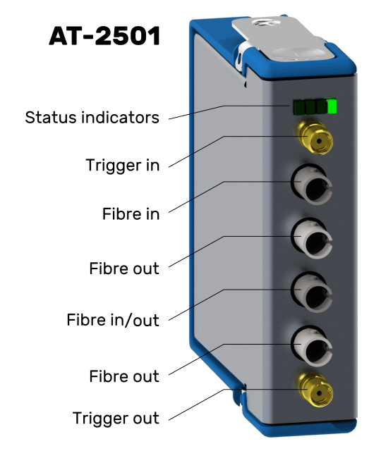
© Copyright 2021 ANGARA TECHNOLOGY - All Rights Reserved

AT-2501 Connectors

AT-2501
Optical Trigger Distribution Module


Please contact us for specification options and ordering information.

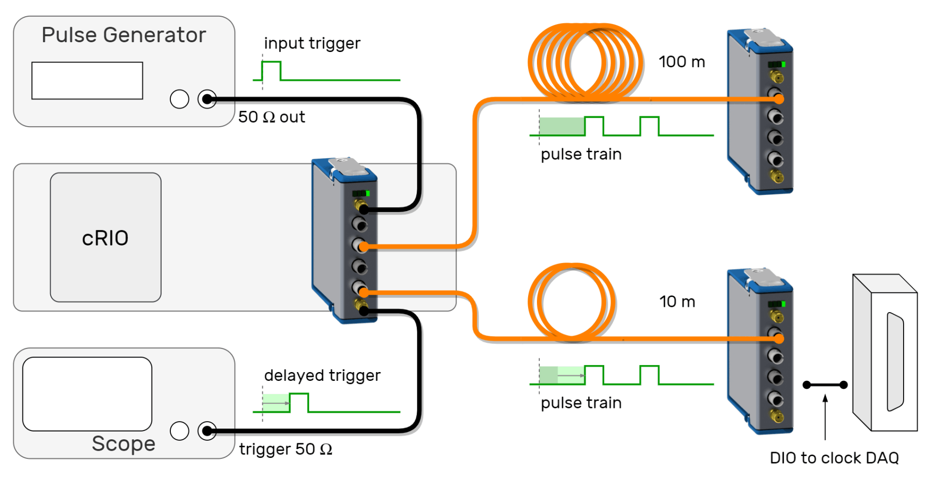
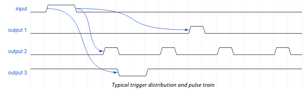
The AT-2501 is a CompactRIO module for distributing electrical and optical trigger signals between cRIO chassis and other instruments. Each output has adjustable delay, pulse-width, polarity and pulse-train generation. The optical connectors are configured as two inputs and two outputs.

Features 

· Fibre-optic input and output: trigger or data
· Impedance-matched trigger input and output
· Precise signal-based synchronisation (2.5 ns rms jitter)
· Minimal programming to build complex trigger regimes
· Can synchronise with precision clocks (GPS, White Rabbit etc)
· Choice of fibre-optic connectors: ST or SMA
· Optical communication distance greater than 1 km possible 

Application Examples

Trigger distribution with delay compensation

AT-2501 Trigger Module in Setup
Typical trigger distribution example

Digital communication bridging potential differences

AT-2501 Trigger Module Data Communication

Industries

  • Science research labs 
  • Large physics facilities
  • Energy/electrical network infrastructure
  • Test and measurement labs
  • Medical physics installations
  • Materials testing labs

Applications

  • Master trigger distribution
  • Trigger local instrumentation via electrical connection
  • Trigger remote cRIO chassis via fibre optic connection
  • Ground loop elimination
  • Electrical isolation between cRIO chassis at different potentials (HV applications)
  • DAQ synchronisation between multiple cRIO chassis with propagation delay compensation
  • Optically-coupled communication (RS232, RS485 etc) when using FPGA mode
  • Complementary to local cRIO master clocks
  • Optically-isolated high-speed digital IO
  • Time-based or signal-based synchronisation
  • Cost-effective method to synchronise (signal-based) with PXI chassis (SPEXI* and future FMC OTD card)
  • Generate delays, pulse trains etc with simple programming - no complex coding required

    *SPEXI: Simple PXI express FMC Carrier Board (SPEXI) CERN OHWR project

Specifications*

Inputs
· TTL (50 Ohm switchable)
· Optical (1 or 2), 820 nm
· cRIO FPGA (via DIO) 


Outputs
· TTL (can drive 50 Ohm)
· Optical (2 or 3) 820 nm
· cRIO FPGA (via DIO)

Maximum Symbol Rate
· 40 MBd (FPGA-controlled)

Pulse Width 
· 10 ns min, 42s max.  
· Width step size : 10 ns

Delay
· 10 ns min, 42s max 
·  Delay step size : 10 ns

Edge Jitter 
· 2.5 ns rms typical

Pulse Train
· 2 to 65536 pulses
· Adjustable delay, width and pulse rate

Polarity
· Rising or falling edge triggered 

Electrical connectors
· SMA

Fibre connectors 
· ST or SMA

Code librairies
· Library and examples provided for LabVIEW

Location

  • ANGARA TECHNOLOGY
    Rampe de Choully 2
    CH-1242 Satigny

Follow us on 

Contact

  • info@angaratech.ch

  • +41 78 694 64 57